📅 1 Feb 2021
A Battery-Powered Tootbrush Timer for Children
After a few posts focused on how I set up this website, I want to write about something completely different this time.
I’ve been dabbling with Arduinos for quite a few years and I’ve made a sizeable amount of personal projects. However, I’m very lazy ☺️, so I’ve never properly documented any of them. So I want to get started now. Today’s post is about the most recent project: a battery-powered toothbrush timer for my kids.
The reason for making this is that my kids are brushing their teeth with normal toothbrushes but are always fighting and arguing about who has brushed long enough and who didn’t. So I decided to try and make a simple micro-controller-based timer that would end those heated arguments. 😉
The objective is to create a timer that starts when you press a button (or more buttons in case of more children). It should then run for a hardcoded preset time (e.g. 2 minutes) which is split up into four equal parts: for the top-left, top-right, bottom-left and bottom-right. Per button, the brushing time will be indicated by four blinking LEDs, which will come on consecutively after earch quarter of the time. The final requirement is that the whole thing should be able to run on one battery charge for at least a few months.
Finished timer
Let’s start by showing off the finished state of the project.
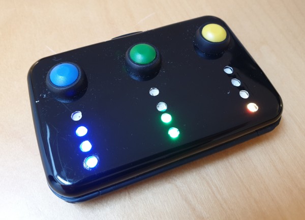
I think it came out pretty nice, especially given the fact that I don’t have professional tools. I only used a standard power drill and a Dremel. The only remaining thing I still want to do is to put a piece frosted plastic foil between the pixels and the inside of the case.
This is the Bill of Materials:
- a case (e.g. business card holder)
- a slim battery holder (3×AAA)
- a piece of circuit board: perfboard/veroboard
- ATTiny85
- (optional) DIP8 socket for ATTiny85
- Neopixel strip (e.g. SK6812-based pixels)
- 3× momentary 2-terminal push button
- 2-pin terminal block connector
- 6, 7 or 9-pin terminal block connector (depending on sharing of wires)
- 3× 100pF ceramic capacitor
- 2× 100µF electrolytic capacitor
- 10kΩ resistor
- 470Ω resistor
Casing, buttons and LEDs
As casing, I used a business card case. I had picked up a handful of these a few years ago. I thought they could come in handy for small Arduino projects. The frame and the hinge of the case are actually made out of 2-3 millimeter thick plastic, with two metal shells on the outside. Originally, the case had accordion-like sections on the inside, which were easy to remove.
Next, I drilled the holes for the buttons and the individual LED pixels using a standard power drill. This was pretty tricky to do very precisely since the drill bit had the tendency to slide around on the smooth metal surface. After that, I milled out a strip of plastic behind each set of 4 holes such that the pieces of neopixel strip would fit nicely into those slots.
I decided to go for three distinctive button cap colours and matching LED colours. After that, wires were soldered to the buttons and the LED strip sections. Then the buttons, LEDs and battery case were mounted to the case. The result looks like this.
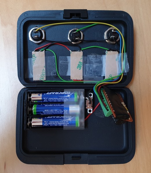
Note that this picture also shows the circuit board (wrapped in insulation tape to avoid short circuits) which we’ll focus on now.
Electronics
Since the whole thing requires only a few in- and outputs and is supposed to be very low-power, I’ve gone for an ATTiny85 microcontroller. In deep sleep mode, this chip uses less power than the self-discharge rate of standard batteries, so it should be perfect for this project. Note that I’m using a bare microcontroller, not an ATTiny-based board. This is done on purpose because all those boards have voltage convertors on them which will draw a constant current, draining the batteries within a few hours or days.
In the past I’ve used KiCad to design PCBs for projects.
However in this case, it would be extremely expensive to design and order a custom PCB for this project. It makes more sense to use a piece of perfboard/veroboard for this. On the other hand, I have had a few bad experiences when not planning the wiring and layout beforehand. It’s not nice discovering that you made a stupid wiring-up mistake after spending an hour soldering everything together. So this time I wanted to make sure to have a nice wiring schedule done before I started soldering.
I could have used KiCad, but it would have taken a lot of time to have all the components clip to the perfboard grid and to plan out which strips should be cut and/or connected in which spots. Luckily, after some searching I found VeroRoute. This tool is like a simple version of KiCad, which automatically snaps to grid. Moreover, it combines the schematic and layout design into one step; which makes sense for very simple perfboard circuits.
The result is the following schematic/layout:
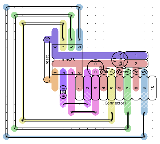
In this layout, the thick coloured strips are connections which are made through the board’s native copper strips, while the thinner lines are connections to be made through wires (preferably more direct than drawn here 😉).
Before we move on, let’s do a very brief run-through of the circuit. Firstly, we’re going to connect the ATTiny directly to the battery, since using power conditioning circuits would drain the battery more than the actual microcontroller. However, to at least have some sort of power conditioning, we’ll put a 100µF cap across the battery plus and minus terminals (indicated by 1 and 2 in the middle right of the picture).
The three buttons are connected to pins 5, 6 and 7 of the ATTiny with a 100nF debouncing cap between the signal and ground lines for each.
The LED strip is a bit more complicated. Each of the pixels has a plus, minus and signal connection which are all series connected. Each of the pixels in the strip is actually a tiny microcontroller in its own. This is because the colour of the pixel is set by sending a particular code through the signal line, with each pixel identifying the relevant colour by a strict timing pattern. The main drawback, however, is that each of the pixels will keep drawing power, even when the LED is off. In order to overcome that, we’ve wired up the plus of the LED strip to pin 3 of the ATTiny85, such that we can completely switch off the power to the strip. Note that there’s an additional 100µF cap between the ground line and this pin in order to condition the voltage. This is needed because a neopixel strip can draw quite a lot of power at power-on.
The result looks like this.
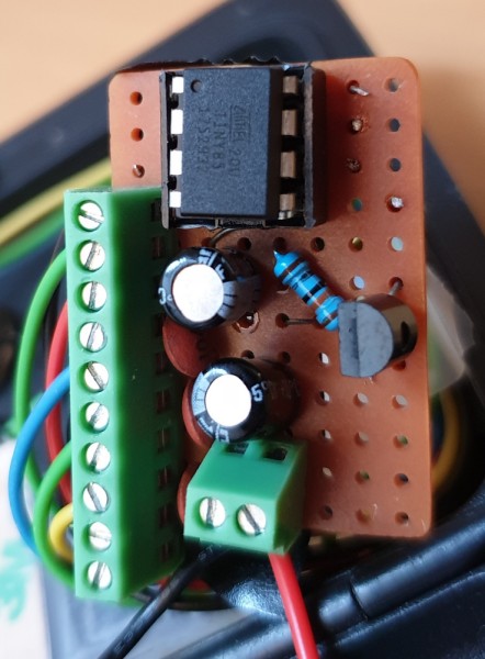
SIDE REMARK: Before I ended up connecting the power line of the LED strip directly to the ATTiny85, I was playing around with connecting it through a PMOS transistor. However, I ended up with latch-up-like problems because the FET was too ideal as a switch, leaving the LED power line floating. ☺️ After some measurements, it turned out that the strip was drawing significantly less current than the maximum that an ATTiny pin can handle. That’s why I decided to wire it up directly. NB: You can still see the unused transistor and resistor in the picture above.
Arduino Code
The only thing left now is programming the ATTiny85. I’ve used the standard Arduino environment. You can find the full code at the bottom of this post. Let’s just go over the dependencies and a few of the interesting bits.
Hardware setup:
- hardware: a USBASP interface or an Arduino UNO board to be used as ISP programmer. Don’t forget to select the correct “programmer” settings in the Arduino software.
- An ATTiny board definition.
Next, the correct fuse settings should be flashed to the ATTiny85: we want to use the 8MHz internal oscillator and we also want to disable the brown-out detector (BOD). The fuse settings can be calculated using this tool. The fuse settings are stored in a settings file inside the Arduino dot-directory.
Software:
- Adafruit NeoPixel library; should be installable through the Arduino library interface.
- The code contains a
deep_sleep()function which switches off all unnecessary internal components of the ATTiny85, switches off the power to the NeoPixels and then puts the controller to sleep. - The code uses pin change interrupts to wake up the microcontroller when one of the three buttons is pushed. Most of the signal debouncing is done in hardware through the 100nF caps. It’s gets quite tricky to combine pin change interrupts with software debouncing only.
All there is left now is to edit the pre-compiler variables at the top of the code to configure pin connections, brush time etc., and that’s it!
So, finally, here is the full Arduino code. I might set up a GitHub repository for this in the future.
// Copyright 2020 <bart at mogwai dot be>
//
// Details about settings and hardware for brush_timer
//
// microcontroller: attiny85 using https://raw.githubusercontent.com/damellis/attiny/ide-1.6.x-boards-manager/package_damellis_attiny_index.json
// programmed with USBasp
//    on a fresh attiny85:
//      - first short J3 on USBasp to force it to low speed (needed because default attiny85 runs at 1MHz);
//      - then write bootloader with fuse settings mentioned below;
//      - for subsequent programming J3 can be left open again
//
// fuse settings (8MHz internal + disabled BOD): low=0xe2, high=0xdf, extended=0xff
//
// using libraries: adafruit_neopixel (through library manager)
//
// pin connection mapping: pin (arduino pin number, port number)
//     1 (5, PB5): reset pin connected to PWR through 10k resistor
//     2 (3, PB3): connected to control pin of LED strip
//     3 (4, PB4): connected to LED power (plus-terminal of neopixel strip)
//     4 (GND): connected to - of 3xAAA battery pack
//     5 (0, PB0): connected to yellow button
//     6 (1, PB1): connected to green button
//     7 (2, PB2): connected to blue button
//     8 (VCC): connected to + of 3xAAA battery

#include <avr/sleep.h>
#include <avr/wdt.h>
#include <avr/interrupt.h>

#include <Adafruit_NeoPixel.h>

// To which pins are the buttons connected?
#define BUTTON1 0
#define BUTTON2 1
#define BUTTON3 2

// Which pin will be providing power to the NeoPixels?
#define LED_POWER   4

// Which pin on the Arduino is connected to the signal line of the NeoPixels?
#define LED_PIN     3

// How many NeoPixels are attached to the Arduino?
#define LED_COUNT  12

// NeoPixel brightness, 0 (min) to 255 (max)
#define BRIGHTNESS 20

// How long to brush and to blink?
#define BRUSHINGTIME 90000 // one and a half minute
#define BLINK_TIME 500     // time between two blinks is twice this

// Which colours to use?
#define COLOR_OFF strip.Color(0,   0,     0) // aka "off"
#define COLOR1    strip.Color(255, 255,   0) // aka "yellow"
#define COLOR2    strip.Color(0  , 255,   0) // aka "green"
#define COLOR3    strip.Color(0,   0,   255) // aka "blue"

// Declare our NeoPixel strip object:
Adafruit_NeoPixel strip(LED_COUNT, LED_PIN, NEO_GRB + NEO_KHZ800);
// Argument 1 = Number of pixels in NeoPixel strip
// Argument 2 = Arduino pin number (most are valid)
// Argument 3 = Pixel type flags, add together as needed:
//   NEO_KHZ800  800 KHz bitstream (most NeoPixel products w/WS2812 LEDs)
//   NEO_KHZ400  400 KHz (classic 'v1' (not v2) FLORA pixels, WS2811 drivers)
//   NEO_GRB     Pixels are wired for GRB bitstream (most NeoPixel products)
//   NEO_RGB     Pixels are wired for RGB bitstream (v1 FLORA pixels, not v2)
//   NEO_RGBW    Pixels are wired for RGBW bitstream (NeoPixel RGBW products)

bool timer1_on = false;
bool timer2_on = false;
bool timer3_on = false;

unsigned long timer1 = 0;
unsigned long timer2 = 0;
unsigned long timer3 = 0;

void setup() {
  //first switch off control and power of LED strip
  pinMode(LED_PIN, OUTPUT);
  digitalWrite(LED_PIN, LOW);
  pinMode(LED_POWER, OUTPUT);
  digitalWrite(LED_POWER, HIGH);
  strip.begin();           // INITIALIZE NeoPixel strip object (REQUIRED)
  strip.clear();
  strip.show();            // Turn OFF all pixels ASAP
  strip.setBrightness(BRIGHTNESS); // Set BRIGHTNESS
  pinMode(BUTTON1, INPUT_PULLUP);
  pinMode(BUTTON2, INPUT_PULLUP);
  pinMode(BUTTON3, INPUT_PULLUP);
  delay(500); // wait a bit for everything to settle
}

void loop() {
  unsigned long now = millis();

  if (digitalRead(BUTTON1) == LOW) {
    timer1_on = true;
    timer1 = 2*BLINK_TIME*(now/(2*BLINK_TIME));
    for (unsigned long i=0; i<4; i++) strip.setPixelColor(i, COLOR_OFF);
  }
  if (timer1_on) {
    unsigned long segment = min(4*(now-timer1)/BRUSHINGTIME,3);
    for (unsigned long i=0; i<=segment; i++) {
      strip.setPixelColor(i, COLOR1);
    }
    if (((now-timer1)/BLINK_TIME)%2 == 0) {
      strip.setPixelColor(segment, COLOR1);
    } else {
      strip.setPixelColor(segment, COLOR_OFF);
    }
  }

  if (digitalRead(BUTTON2) == LOW) {
    timer2_on = true;
    timer2 = 2*BLINK_TIME*(now/(2*BLINK_TIME));
    for (unsigned long i=4; i<8; i++) strip.setPixelColor(i, COLOR_OFF);
  }
  if (timer2_on) {
    unsigned long segment = min(4*(now-timer2)/BRUSHINGTIME,3)+4;
    for (unsigned long i=4; i<=segment; i++) {
      strip.setPixelColor(i, COLOR2);
    }
    if (((now-timer2)/BLINK_TIME)%2 == 0) {
      strip.setPixelColor(segment, COLOR2);
    } else {
      strip.setPixelColor(segment, COLOR_OFF);
    }
  }

  if (digitalRead(BUTTON3) == LOW) {
    timer3_on = true;
    timer3 = 2*BLINK_TIME*(now/(2*BLINK_TIME));
    for (unsigned long i=8; i<12; i++) strip.setPixelColor(i, COLOR_OFF);
  }
  if (timer3_on) {
    // this LED strip is mounted the other way around than 1 and 2, so need to swap pixels around
    unsigned long segment = 11-min(4*(now-timer3)/BRUSHINGTIME,3);
    for (unsigned long i=11; i>=segment; i--) {
      strip.setPixelColor(i, COLOR3);
    }
    if (((now-timer3)/BLINK_TIME)%2 == 0) {
      strip.setPixelColor(segment, COLOR3);
    } else {
      strip.setPixelColor(segment, COLOR_OFF);
    }
  }

  strip.show();

  // end of loop action
  if (timer1_on && ((now-timer1) > BRUSHINGTIME)) { timer1_on = false; timer1 = 0; for (unsigned long i=0; i<4; i++) strip.setPixelColor(i, COLOR_OFF);}
  if (timer2_on && ((now-timer2) > BRUSHINGTIME)) { timer2_on = false; timer2 = 0; for (unsigned long i=4; i<8; i++) strip.setPixelColor(i, COLOR_OFF);}
  if (timer3_on && ((now-timer3) > BRUSHINGTIME)) { timer3_on = false; timer3 = 0; for (unsigned long i=8; i<12; i++) strip.setPixelColor(i, COLOR_OFF);}

  if (!timer1_on && !timer2_on && !timer3_on) {
    deep_sleep();
  }
}

void deep_sleep() {
  //switch off all leds and power down led strip
  strip.clear();
  strip.show();
  delay(200);
  digitalWrite(LED_POWER, LOW);
  digitalWrite(LED_PIN, LOW);

  GIMSK |= _BV(PCIE);                     // Enable Pin Change Interrupts
  PCMSK |= _BV(PCINT2);                   // Use PB2 as interrupt pin
  PCMSK |= _BV(PCINT1);                   // Use PB1 as interrupt pin
  PCMSK |= _BV(PCINT0);                   // Use PB0 as interrupt pin
  ADCSRA &= ~_BV(ADEN);                   // ADC off
  set_sleep_mode(SLEEP_MODE_PWR_DOWN);    // replaces above statement
  sleep_enable();                         // Sets the Sleep Enable bit in the MCUCR Register (SE BIT)
  sei();                                  // Enable interrupts
  sleep_cpu();                            // sleep

  cli();                                  // Disable interrupts
  PCMSK &= ~_BV(PCINT2);                  // Turn off PB2 as interrupt pin
  PCMSK &= ~_BV(PCINT1);                  // Turn off PB1 as interrupt pin
  PCMSK &= ~_BV(PCINT0);                  // Turn off PB0 as interrupt pin
  sleep_disable();                        // Clear SE bit
  ADCSRA |= _BV(ADEN);                    // ADC on

  sei();                                  // Enable interrupts

  digitalWrite(LED_PIN, LOW);
  //switch power to led strip back on and initialize
  digitalWrite(LED_POWER, HIGH);
  strip.clear();
  strip.show();            // Turn OFF all pixels ASAP
} // deep_sleep

ISR(PCINT0_vect) {
  // This is called when the interrupt occurs
  // do nothing; everything will be handled in main loop
}
💬 Looking for comments?
I don't have comments on this site as they're difficult to manage and take up too much time. I'd rather concentrate on producing content than managing comments.
Instead of leaving a comment, feel free to contact me ✉️ contact me instead.